
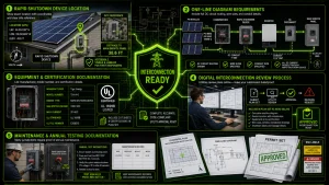
Rapid Shutdown (NEC 690.12) Compliance in Solar Plans: 2026 Design Requirements & Labeling
Why Rapid Shutdown Compliance Matters—And How It Protects Your Bottom Line
Understanding rapid shutdown compliance separates professional solar installers from those who struggle with interconnection delays and failed inspections. In fact, the National Electrical Code updates now demand that every photovoltaic system meet strict NEC 690.12 requirements. Here’s the reality: improper implementation costs money through rework, delays, and safety violations. Fortunately, the solution is straightforward. By embedding these requirements into your design process before permitting begins, you avoid costly revisions.
This guide walks you through everything you need to know about rapid shutdown compliance. Moreover, you’ll learn exactly how to design compliant systems, label them correctly, and pass inspections on the first attempt.
Understanding NEC 690.12 and Why It Exists
First, let’s establish what NEC 690.12 actually requires. The standard mandates that all DC circuits on the DC side of a photovoltaic system must shut down within ten seconds of activation. Furthermore, firefighters need this capability. When a structure burns, they cannot safely work around energized solar equipment. Without this protection, firefighters face dangerous voltage from the panels themselves.
Think of it like this: your home has a main electrical panel with breakers. Similarly, solar systems need an equivalent barrier. That barrier is your rapid shutdown solution. Additionally, the code changed because early solar deployments lacked this protection, leaving first responders exposed to unnecessary risk.
Two Approved Approaches for Rapid Shutdown Compliance
Notably, installers typically use one of two strategies: module-level shutdown or array-level shutdown with compliant wiring methods. Let’s examine each option.
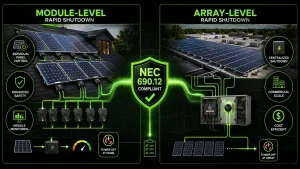
Module-level solutions install a shutdown device on every panel. For example, micro-inverters and DC-optimizers like SolarEdge, Enphase, and Tigo work this way. As a result, power runs through the device, and when de-energized, the panel stops sending current downstream. In addition to safety benefits, this approach offers monitoring per module.
Array-level solutions, on the other hand, keep large panels as-is but use compliant combiner box shutdown devices. Therefore, this method works well for larger residential and commercial installations where microinverter costs don’t pencil out. Ultimately, both approaches satisfy rapid shutdown compliance. Your choice depends on system size, budget, and client preference. Neither is inherently superior—each solves the problem within NEC 690.12 parameters.
Design Requirements: What You Must Include in Your Plans
Significantly, your permit-ready plans must document your rapid shutdown compliance strategy explicitly. Moreover, inspectors won’t assume—they’ll verify it in writing. Here’s exactly what you need.
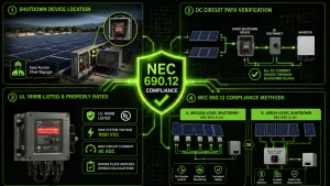
First, identify where your shutdown device sits. For instance, on rooftop systems, that’s usually a combiner box or inline controller accessible by first responders. Furthermore, in attic installations, the device must sit in a safe, visible location with clear signage. Second, show the DC circuit path. Essentially, tracing current from the first module through your rapid shutdown device and into the inverter proves that all DC current passes through your shutdown equipment. Consequently, a gap in this path—say, a direct bypass around the device—breaks compliance immediately.
Third, confirm your device is UL 1699B-listed and rated for your system’s voltage and current. Indeed, an undersized device creates a fire risk. Meanwhile, an oversized device is wasteful but acceptable. Additionally, the rating plate must match your design calculations. Finally, verify your shutdown method is listed under NEC 690.12(A), (B), (C), or (D). Most installers use the listed module approach (A) or array DC switch (B). Notably, knowing which method applies to your installation prevents design rejection.
Labeling Standards: Where Signs Go and What They Must Say
Importantly, NEC 690.12 demands warning labels at every shutdown location. Indeed, inspectors treat missing labels as non-compliance, even if the device itself is correct.
Your main rapid shutdown device needs a permanent, weather-resistant label. Specifically, it should read: “RAPID SHUTDOWN DE-ENERGIZING SWITCH“ in white lettering on red background, minimum four inches high. Furthermore, mount it directly above or beside the switch, at eye level. On the roof, near the combiner or controller, add a second label identifying the rapid shutdown device model and location. Consequently, this label helps firefighters locate the control on an unfamiliar roof.
Additionally, inside the home at the main service panel, install a label pointing to the rapid shutdown location with an arrow. For example: “DC Rapid Shutdown at [Roof/Attic]—See Plan Set” works perfectly. Therefore, these labels aren’t bureaucratic overhead. Rather, they’re communication tools that save lives. A firefighter arriving at your installation at 2 a.m. in smoke and chaos needs immediate clarity.
Common Design Mistakes That Trigger Inspection Failures
First, let’s address the most common error.
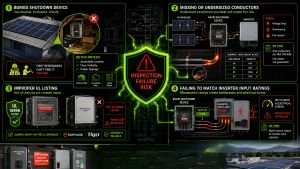
Mistake 1: Burying the shutdown device. Placing your combiner box in an attic corner or basement closet seems convenient. However, inspectors and firefighters won’t find it. Instead, always install shutdown equipment in an accessible, clearly marked location. Exterior south-facing walls, accessible attics, or utility rooms work. Buried conduit? Definitely not.
Mistake 2: Missing or undersized conductor sizing. Your shutdown device DC input/output terminals require conductors sized per NEC 240.4(B). Consequently, an undersized conductor creates voltage drop, overheating, and fire risk. Therefore, use tables—don’t guess wire size.
Mistake 3: Improper UL listing. Off-brand devices that look like rapid shutdown equipment may lack UL 1699B certification. Furthermore, use only manufacturers on the UL database. Meanwhile, micro-inverter brands like Enphase and Tigo are solid. Importantly, lesser-known combiner box brands require verification before design.
Mistake 4: Failing to de-rate inverter input terminals. If your inverter input terminals accept only 100 amps but your rapid shutdown device outputs 150 amps, you’ve created a bottleneck. Consequently, the system still passes rapid shutdown compliance but creates electrical stress. Therefore, size your device to match inverter input capacity.
Integration with Your 2026 Plan Set and Interconnection
Here’s why rapid shutdown compliance matters beyond code compliance: interconnection authorities increasingly demand proof in your one-line diagrams.
Your electrical plan set should show: exact location of the rapid shutdown device with X/Y coordinates, DC circuit routing with wire size and conduit diameter, equipment manufacturer and model number, UL certification number, distance from the main service panel to shutdown location, and labeling locations and specifications. Moreover, this detail prevents back-and-forth requests from utilities. Indeed, modern interconnection reviews happen online—inspectors can’t ask clarifying questions on site. Therefore, your plans must be bulletproof.
Additionally, some jurisdictions now require maintenance documentation. Thus, include one page showing how an owner or service technician verifies their rapid shutdown device functions annually. For instance, a simple label on the device might read: “Test Annually—Press Red Button” if your device includes a manual test button.
Moving Forward: Making Rapid Shutdown Compliance Routine
The best solar installers treat rapid shutdown compliance not as a checkbox but as a design principle. Furthermore, start every project by choosing your shutdown method. Additionally, document it immediately. As a result, build it into your template one-lines and electrical plans.
Doing so makes the process automatic. Your crews know the standard location for devices. Therefore, your electricians expect rapid shutdown labeling on every job. Consequently, inspectors recognize your familiarity with the code.
Conclusion
Mastering rapid shutdown compliance and NEC 690.12 requirements is non-negotiable in modern solar installation. Whether you’re designing residential systems or large commercial arrays, a properly compliant plan protects your crews, clients, and first responders.
EnergyScape Renewables provides engineering services and PE-stamped plan sets that bake rapid shutdown compliance into every design from the outset. Our electrical engineers verify your system against current NEC standards, coordinate with interconnection authorities, and deliver plans that pass inspection on the first review.
For installers who want to strengthen their in-house engineering, Sunscape Solar CRM platform helps you manage plan design workflows, track compliance requirements by jurisdiction, and document rapid shutdown details for every project. Learn how EnergyScape Renewables and Sunscape Solar accelerate your compliance process.
sjayakanth@energyscaperenewables.com