
Solar Grounding vs Bonding: Why Anodized Frames Fail Tests
Solar Grounding vs Bonding: Why Anodized Frames Fail Continuity Tests
Solar grounding vs bonding describes two separate paths. Bonding ties metal parts together through an equipment grounding conductor so fault current trips the breaker. Grounding connects the system to earth through a grounding electrode conductor. Anodized module frames fail continuity tests because the anodized coating insulates. Listed hardware must pierce it to reach raw aluminum.
An inspector places two probes on the same module frame, an inch apart. The meter reads OL. Nothing broke, and the crew missed nothing. That reading simply proves the anodized aluminum frame is doing what it was engineered to do: insulate.
Yet the cost of getting this wrong is steep. A NYSERDA NY-Sun review found grounding deficiencies in 53% of inspected systems, making it the largest single cause of re-inspection and PTO delay. Meanwhile, roughly 23–26% of installs fail their first AHJ inspection, and a reinspection pushes the job out one to three weeks.
So let’s clear up the confusion, then fix it at the design stage where it belongs.
Solar Grounding vs Bonding: EGC and GEC Side by Side
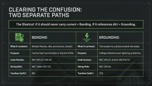
| Bonding (EGC path) | Grounding (GEC path) | |
|---|---|---|
| What it connects | Module frames, rails, enclosures, conduit | The system to a physical earth electrode |
| Purpose | Carries fault current back to trip the OCPD | Voltage reference and lightning protection |
| Code section | NEC 690.43, 690.45 | NEC 690.47, Article 250 Part III |
| Sizing rule | NEC Table 250.122 | NEC 250.66 |
| Touches earth? | No | Yes |
Here’s the shortcut your crew can remember. If the metal should never carry current, that’s bonding. If it references dirt, that’s grounding. Mixing up the two remains one of the most common design errors, and inspectors catch it fast.
Why Anodized Frames Fail Continuity Tests
Modern modules use an anodized aluminum frame, and that coating acts as a powerful electrical insulator. Therefore, a probe on the surface reads open even across two points on the same rail.
To bond the module, hardware must breach that layer. UL 2703 listed mid-clamps with integrated bonding pins do this as you torque them, driving stainless pins through the anodization into raw aluminum underneath.
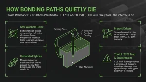
Know the target number, because your inspector does: UL 1703, UL 61730, and UL 2703 all cap bonding path resistance at 0.1 ohms, verified by passing twice the fuse ampere rating through the joint and measuring voltage drop.
Four Ways a Bonding Path Quietly Dies
The wire rarely fails. The interfaces do.
Star washers relax over time. Bolt pretension concentrates load at the small washer protrusions. That causes compressive yield in the aluminum frame and progressive relaxation, which retightening cannot reverse. Burndy testing — short-time current per UL 467 plus 500-hour salt fog per ASTM B117 — recorded erratic resistance and, in some samples, complete loss of continuity. The install passed. Two winters later, it won’t.
Impact drivers replace torque wrenches. Crews strip grounding pins or under-torque clamps, which breaks the UL 2703 path immediately.
Rail splices go unbonded. Jumpers must bridge every mechanical splice so the row behaves as one conductor. A single miss can stall PTO for weeks.
Hardware gets substituted. Third-party lugs, drilled rails, or missed torque specs void the listing outright.
The UL 2703 Listing Trap
This one catches experienced EPCs.
UL 2703 covers separate criteria — mechanical loading, grounding and bonding, and fire classification. A component may carry the mark for only one of them. Consequently, you must verify the actual certification on UL Product iQ rather than assume the mark covers bonding.
The module matters too. Even inside a listed system, the specific module has to be evaluated with that racking. Frame thickness and clamp zone mismatches trigger more plan check delays than most installers expect. Mixing brands voids the system listing, and expanding a listing to cover new module types takes four to eight weeks.
Now connect that to procurement. Domestic content rules keep forcing module swaps mid-project. Every swap after your plan set is stamped risks breaking the pairing, and SolarAPP+ will reject it — that’s the R72 error.
What NEC 2026 Actually Changed
Less than you’d expect, which is exactly the trap.
In the 2026 NEC, 690.47(A) now points straight to Part III of Article 250, and the panel deleted 690.47(B) without changing any enforceable requirement. The architecture of 690.41 through 690.47 held.
In short, the practice stayed put but the citation moved. Since states like North Carolina, Washington, and Texas amend NEC 2023 locally, a multi-state installer may cite three editions in one month. That risk lives on the plan set, not the roof.
Your Pre-Inspection Bonding Checklist
- Confirm the racking is UL 2703 listed for grounding and bonding on UL Product iQ.
- Verify the installed module appears in the manufacturer’s evaluated module list.
- Torque every clamp with a calibrated wrench and log the values.
- Install a bonding jumper at each rail splice.
- Use purpose-built bonding washers instead of generic star washers.
- Size the EGC per Table 250.122 for every circuit.
- Land the GEC on the correct terminal and bond raceways at both ends.
- Match the as-built to the stamped plan set, including any module substitution.
Inspectors now review torque logs, confirm listings, and run micro-ohm meters across splices. Come prepared.
Permitting already costs roughly $1.00 per watt, or $6,000 to $7,000 on a typical residential job, as we covered in How to Pass Solar Inspection First Time. Every avoided reinspection protects that margin directly.
Solar Grounding vs Bonding: Get Grounding Right Before the Truck Rolls
Bonding failures aren’t solved on the roof. They’re prevented at the desk.
Energyscape Renewables delivers PE-stamped plan sets and single-line diagrams with EGC sizing, GEC connections, and racking-to-module listing pairs already matched to your AHJ’s code edition. Every solar service except the installation itself.
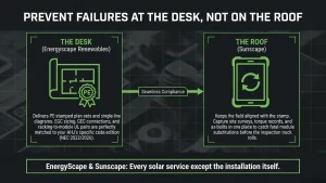
Sunscape keeps the field aligned with the stamp. Capture site surveys, torque records, and as-builts in one place, so a module substitution surfaces before it becomes a failed inspection.
Frequently Asked Questions: Solar Grounding vs Bonding
Why does my solar panel frame show no continuity?
The anodized coating insulates the aluminum. You need listed bonding hardware that pierces the coating and reaches raw metal underneath to create a valid path.
Can racking serve as the equipment grounding conductor?
Yes, when the system is listed and identified for that use under UL 2703, installed per the manual, with bonding jumpers across every rail splice.
What resistance should a solar bonding path measure?
0.1 ohms or less. UL 1703, UL 61730, and UL 2703 all set that limit, tested at twice the fuse ampere rating.
Does swapping module brands void my racking listing?
It can. The module must appear in the racking manufacturer’s evaluated list, and mixing brands across rails, clamps, or lugs voids system listings.
sjayakanth@energyscaperenewables.com