
Transformerless Inverter Grounding: Never Add a DC Ground
Transformerless Inverter Grounding: Never Add a DC Ground
A crew wraps a 9.6 kW residential job on Friday. On Monday, the inverter refuses to connect and throws an isolation fault. The tech swaps the unit, and the fault returns. Nothing was wrong with the hardware. Someone had landed a grounding electrode conductor on the DC negative, because that is how they learned it. Transformerless inverter grounding works the opposite way, and this one habit costs installers truck rolls, failed inspections, and warranty claims they never needed to file.
Why Transformerless Inverter Grounding Confuses Experienced Crews
Older transformer-based systems required a bonded DC conductor. Modern non-isolated inverters do not. So the muscle memory that kept you compliant in 2012 now gets you a correction notice. In fact, confusing the equipment grounding conductor with the DC negative is a serious error and a common cause of inspection failure.
Separate These Three Terms and the Argument Ends
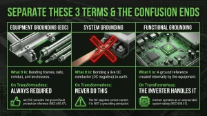
Most job-site disputes collapse three different ideas into one word. Pull them apart, and the confusion disappears.
| Term | What it means | On a transformerless inverter |
|---|---|---|
| Equipment grounding (EGC) | Bonding frames, rails, conduit, and enclosures | Always required |
| System grounding | Bonding a live DC conductor to earth | Never do this |
| Functional grounding | A ground reference the inverter creates internally | The inverter handles it |
Print that table and hang it in the warehouse. The DC negative carries current, so it is not a grounding conductor.
What NEC 690.41 and 690.47 Actually Require
The rules settled in the 2017 cycle, and they have not moved much since.
NEC 690.41(A) lists the acceptable forms of array system grounding, and for most arrays the inverter provides functional grounding. Crews install the DC circuits with no conductor marked as grounded. Solidly grounded PV now survives only through the narrow exception in 690.41(B).
Then 690.47 finishes the job. For functional grounded systems, the AC equipment grounding conductors running from the inverter to the distribution system may serve as the grounding connection for ground fault protection and for equipment grounding of the array.
Therefore you need no separate DC grounding electrode conductor and no mandatory ground rod at the array. But what about the rod your crews drive anyway? An auxiliary electrode is permitted, though not always required, and you must bond it into the main grounding electrode system to avoid a potential difference between electrodes. An unbonded rod is worse than no rod.
SMA Sunny Boy, SolarEdge SE, and Fronius Primo units are UL 1741-listed transformerless inverters with built-in ground fault detection, and they operate correctly as ungrounded systems. Adding your own DC ground does not reinforce that protection. It defeats it.
What Happens Electrically When You Add a DC Ground
Here is where the code rule becomes something a technician can feel.
Most transformerless inverters run an isolation resistance test, or R-Iso, every morning. The test measures resistance between the current-carrying conductors and ground. A healthy new array reads high, often above 40 MΩ.
Manufacturers then set their own trip points. SolarEdge, for example, reports an isolation error below 600 kΩ on single-phase inverters and below 1 MΩ on three-phase units. The UL 1741 Certification Requirement Decision for ungrounded transformerless inverters calls for a trip below 100 kΩ.

Now bond the DC negative to earth deliberately. Isolation resistance drops to nearly zero, so the inverter does exactly what it was certified to do and refuses to connect. To the tech, it looks like a bad unit. To the inverter, the array looks like a dead short.
Worse, these faults hide. Isolation resistance faults are the most common DC faults in PV arrays, and intermittent ones often send techs on truck rolls in vain, because the fault clears before they arrive.
Repowers: The Transformerless Inverter Grounding Trap
Early-2010s fleets are now hitting inverter end of life, and almost every replacement unit is transformerless. That is not a component swap. Instead, it is a grounded-to-ungrounded conversion, and it triggers scope nobody quoted:
- Remove the GFDI bonding jumper.
- Add a disconnecting means for both DC conductors, since the legacy grounded system only switches one.
- Redraw the single-line diagram, and reprint every label and placard.
Crews who bid a repower like a like-for-like swap discover all of this at inspection instead of at proposal.
Why 2026 Raises the Stakes
The grounding concept has been stable since 2017, but the paperwork around it has not.
The country currently runs four NEC editions at once. Per NFPA enforcement data as of March 1, 2026, 28 states have finished their update process while 10 states on the 2023 edition have started moving toward 2026. NFPA issued the 2026 NEC on August 20, 2025, with a September 9, 2025 effective date. Meanwhile, Arizona, Illinois, Kansas, Nevada, and New York leave adoption to local jurisdictions.
As a result, the same correct design clears review in one city and draws redlines in the next county. Your grounding architecture did not change. The label format did. Check the NFPA enforcement map first, then confirm with the AHJ, as we cover in our guide to verifying the NEC edition your AHJ enforces.
Your Five-Line Pre-Submission Check
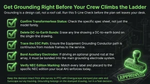
Run this before any plan set leaves your desk:
- Confirm the inverter is transformerless. Check the spec sheet, not the model family.
- Delete any DC-to-earth bond shown on the drawing.
- Trace the EGC path from module frames to the service, without breaks.
- Bond any auxiliary array electrode into the main grounding electrode system.
- Match every label to the edition your AHJ enforces today.
For the rest of the submittal package, use our solar single-line diagram checklist and our breakdown of solar plan set costs.
Get Grounding Right Before Your Crew Climbs the Ladder
Grounding is a design call, not a roof call. It belongs on the plan set, drawn and labeled for the edition your inspector actually holds.
Energyscape Renewables delivers stamped plan sets that spell out the grounding architecture, with 24-hour PE stamping across all 50 states and a 99% AHJ and utility approval rate. Send us the survey, and we will send back a set your crew can build from without guessing.
Sunscape keeps that decision intact from survey to PTO. Capture the existing inverter and grounding condition in the site survey app, which matters most on repowers, then track the approved detail through inspection. Book a demo and stop paying for preventable callbacks.
Transformerless Inverter Grounding FAQs
Do transformerless inverters need a ground rod at the array?
No. The AC equipment grounding conductor provides the reference under NEC 690.47. An auxiliary electrode stays optional, though you must bond it to the main grounding electrode system.
Can I bond the DC negative on a SolarEdge or SMA inverter?
No. These inverters run as ungrounded, functional grounded systems. Bonding the negative creates a permanent ground fault, so the inverter will not operate.
Why does my new inverter show an isolation fault after install?
Check for an added DC ground bond before you swap hardware. Also inspect for pinched conductors and moisture at roof penetrations. SolarEdge publishes a field troubleshooting procedure for this.
Is transformerless inverter grounding different under NEC 2026?
The core rules did not change. However, labeling and marking requirements did, so verify your enforced edition.
Who is responsible if the plan set shows a DC ground?
The design carries it. That is why grounding belongs on the stamped drawing, not in a field decision.
sjayakanth@energyscaperenewables.com